Sunday, February 24, 2019

Custom drain wrenches.


There are more than a few styles of drain strainer wrench. There are also several styles of drain strainer. As with most things to do with plumbing, drain strainers have become fairly uniform. In the times before drain strainers became uniform there were some interesting and sometimes beautifully ornate variations. Therein lies the problem. 

Most of the faucets that are sent to me for restoration must first be removed from large heavy fixtures. They have been set on those fixtures for many decades and it is usually no easy task to separate them. One of the most difficult parts to remove is the drain strainer. This is complicated further when the strainer is cast in an ornate pattern that will lend itself to no known style of strainer wrench. Unfortunately, because of this problem, I sometimes receive bent or twisted ornate drain strainers along with the brassware I am to restore.

I do my very best to remedy this and sometimes have interesting results. That is a different blog post though and I will be getting to it soon.

The work I do these days is far down the road of my journeyman experience. At this point I see myself as an artisan and my work is important to me in terms that don't relate to profit. In a way it is simple problem solving and in a way it is using my tools and my skills to manipulate various materials with the goal of preserving and at times recreating what once was.

While I have the time and interest to do this work, most plumbers do not. Nor should they unless they care to, under their own momentum. One thing I do not want to do is make their task more challenging than it needs to be. I expressly want them to have success when it comes time to reinstall the fixtures I am sending back. I am always willing to consult on the reinstallation, though most plumbers don't ask for the help. I probably wouldn't either. I try to provide specifications and measurements when I think it will help. I also try to provide tools at times, especially for unusual drain strainer patterns.

For the most part the drain strainer wrenches I fashion would not successfully remove strainers frozen in place by decades. They should be strong enough to be used as installation tools though. I have made quite a few custom drain wrenches and I am getting better at taking the time to get photos along the way.    


This ornate lavatory drain was made by J.L. Mott. I have seen the pattern several times on drains of basins as well as tubs. This strainer plate has suffered a bit and is no longer truly symmetrical. It is in fair condition though. When I make a tool for a strainer I try to create as many points of contact as I can. I also try to make those points of contact as far out on the radius as I can. That way the stress is shared by more than the usual two points and the points of contact have more potential torque. In this case I have created six points of contact.  I am sending two of these fixtures back and I wanted to make a tool; that would work for both.


Notice the blue tape. the strainer is not symmetrical so the tool fits best when the tape on the tool and strainer align.


What I envisioned for this tool was a PVC cap with a flat face. I found that I did have such a fitting and began my fabrication. The first thing I did was to lay the flat top of the cap onto the strainer face and pencil the pattern of the plate onto the flat surface of the cap. I then put the cap onto the drill press and drilled six 1/8" holes to match up with the centers of the six outlying holes in the strainer. I then drilled these holes larger in preparation for my 1/4 x 20 tap. I will often begin with smaller bits as a way of staying on center when working by eye. Once the holes were drilled and tapped I was ready for screws.    

I selected six 1/4" x 20  steel straight slot screws. I then cut into the straight slots until the slots extended under the heads. That way I could cut the heads off and the screws would essentially be long straight slot set screws. I cut the heads off so that I could mount the screws into my lathe. Then I blunted the sharpness of the screw threads on the lathe to protect the brass from the threads.

With the screws in place I mixed enough epoxy to embed the screws inside of the cap, creating a much stronger tool. At that point I covered the steel screws with shrink wrap intended for wiring, further protecting the brass from the steel.


With the blue tape in alignment the tool fits into the strainer very well. 
The face of the other strainer is near identical because I fabricated it using this strainer as the model. 
Needless to say, the tool fits both as I had hoped.  

Of the three lavatory drain assemblies I received for this project one was different.
Making this tool was much simpler and I did it in my usual way. I was more conscious of getting photos of the process with this tool.


Once I have selected what I will use as the face of my tool I center it on the strainer and mark where it will protrude through. In this case the best fit was found using a 3/4" CPVC coupling. 
Unless one goes very deeply into the brass there are imperfections in the metal, created by decades of exposure to soap and water, that are not reached by polishing. Those imperfections cannot be seen on the polished surface but electroplating may expose them. 
These flaws, along with the remnants of wrench scars, impact marks, and other damage are not things that I remedy. 
In my view, wear that does not impact function lends authenticity to the fixture. 


I often use a hand saw to make my cuts. This time I used a cutoff wheel and my moto tool.
The unmarked and isolated sections represent the spokes of the drain pattern. 


The narrow sections are removed with a needle nose plier.


What remains are six lugs that fit into the pattern of the strainer.

This power tool is an old Montgomery Ward Power Craft.  


This tool will go with the fixture for the convenience of the installer. 


Thursday, February 21, 2019

Replacing J.L. Mott porcelain index buttons


I have just completed my restoration project on a set of vintage J.L. Mott lavatory faucets. One of the challenges I had to overcome was the lack of original porcelain index buttons for the faucet handles.

Finding intact vintage porcelain index buttons is rather difficult. Finding the correct vintage porcelain index button when you need it is nearly impossible.

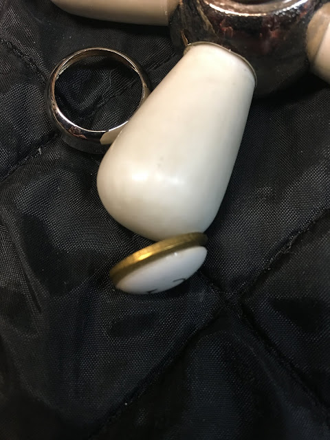
J.L. Mott employed a four part index button style. The brass handle hub had a raised threaded rim that would receive a matching threaded ring. The ring would hold the porcelain index button in place. The forth part would be a disk of thin cardboard. This disk would be placed under the index button to create some friction and be a spacer.

Here are the four parts.  
Early American Standard faucet handles used the same arrangement for their index buttons. I have a modest stock of vintage porcelain index buttons along with some intact orphan handles that I could rob of their index buttons. Reproduction American Standard index buttons however may be had new. I always keep some of these reproduction indexes in stock. They are very faithful to the original, including their distinctive font.

Completing my project necessitated the provision of an index button for each handle. The problem I had was that I didn't have any original Mott buttons. I had a set of four matching buttons that were the correct size but they were too tall to allow the threaded rings to even start, much less seat in. The American Standard buttons were the proper height but they are slightly too small. Small enough to drop through the Mott retainer rings.

With the project essentially done I found myself held up by the lack of two pairs if Mott index buttons. The Standard indexes were very close, close enough to look right if I could find a way to set them firmly into place. My solution to the problem was a little tricky to actually do but it worked.

Among the many vintage repair kits I have in the shop are some assortments of brass friction washers. These are mostly intended to sit under cap gaskets in faucet stem assemblies. I do find other uses for them occasionally. I drew from one of the assortments four brass washers that were too wide to drop though the Mott index button retainer rings, but narrow enough to not inhibit the threading of the retainer onto the raised male thread of the handle hub. These rings would be epoxied onto the down facing sides of the index buttons. The tricky part was getting them properly centered and holding the indexes in place during the process.

I found that the index buttons danced around on the work surface far too much to do the careful epoxy work that was required. I have 1/8" thick crafting tape that is sticky on both sides. I cut a portion of the tape and stuck it down to the work surface. I then pealed off the protective paper from the top side of the craft foam. The double stick foam held the index buttons snugly in place and I was able to work.

I was careful to keep the epoxy off of the downward facing finished sides of the buttons. With a thin coating of epoxy on the unfinished side I was ready to set the rings into place. They had to be centered, but I was able to do this by eye. After each brass washer was in place I added a little more epoxy to the indent created by the washer on the disc of the index.

The next day I was able to assemble my final result.  


Wednesday, February 20, 2019

Replacing J.L. Mott porcelain escucheons.


Plumbing fixture restoration certainly can be challenging. One of the most demanding aspects of it is the need to replace lost or badly damaged parts. It demands all of my skill and creative problem solving at times to simply approximate the original aesthetic appeal of beautifully designed fixtures.


This is especially true when working on L. Wolff or J.L. Mott plumbing fixtures. There is a far smaller pool of salvaged parts available for those manufacturer's products than there is for Crane, Speakman, or Standard brassware.

I have made great progress learning ways to recreate brass parts, but sourcing or recreating porcelain parts remains elusive at best.

I am just wrapping up work on a large project for a home on the other side of the country. All of the fixtures I have been sent were made by The J.L. Mott Company. Two lavatory faucets arrived without china escutcheons or china index buttons. This post is about what I eventually did to provide escutcheons for the fixtures.


I received four faucet valve bodies for the two faucets, two hot and two cold. 
 These threaded brass rings were on two of the valve bodies. 
When I saw them I knew what style escutcheon was originally used to trim the faucet. 
These brass rings are not in good condition, The outside rings are neither perfectly round nor perfectly flat. 


I had a machinist make a new pair for each valve body.
The inner ring is the top mounting nut for the valve assembly. 
The outer ring will be embedded into the china escutcheon. 


Here is a view of the faucet valve body assembly. 
Note the lower nut and gasket for the under side of the faucet deck. 


This photo shows the intended application of the outer ring. 
Some manufacturers used this type of threaded ring to make their escutcheons self attaching. 

Speakman used the same style of embedded ring to make their self attaching escutcheons.
Note that the escutcheon is cast with two flat sides that correspond to the two flat sides of the ring. 
The ring is then plastered into place with Plaster of Paris. 
One distinctive feature of  self attaching escutcheons is the size of the hole on top of the escutcheon. 

The more common way to attach china escutcheons is with a threaded tube and escutcheon retainer nut. 

Note that the packing nut has a female thread to receive the threaded tube.  


The packing nut on the J.L. Mott stem does not have the female thread to receive an escutcheon mounting tube. 
Furthermore, there is not enough height differential between the packing nut and the top of the stem to allow the additional parts. My new stems are replications of the original in all dimensions. 


My task was to select china escutcheons that are wide enough to receive the outer rings and the proper height to both clear the packing nut and leave some amount of stem visible between the handle and the escutcheon. My research brought me to images of Mott fixtures with escutcheons that were low and wide, I knew that I was recreating the original motif fairly accurately. 


The original Mott escutcheons would have had stem size holes. 
The escutcheons that fit my parameters had escutcheon nut size holes. 
To remedy this I selected a set of four escutcheon nuts of the proper size. 
I altered them on my lathe to give them a smooth rounded shoulder. 
In this way I also removed the striations that would allow them to be hand tightened.  

This is the motif I was after.


One of the things I must do is establish a rough-in specification for this faucet. 
I will not be installing it so I must do all in my power to help the installer to be successful. 
The valve body height is driven by the length of the spout inlet tube.  Earlier I set all of the assemblies up in a mock installation. At that time I determined the optimal height of the stem end above the faucet deck. 
Here I have temporarily fastened a wide washer to the stem. 
This will help me to see the height without tilting my tape measure. 

I should mention that I have mounted the valve body to a section of 3/4" chipboard that I sometimes use as a base for my gasket cutter. I know that it is quite flat and true. I drilled a 1-1/8" hole in it expressly for this task. 
I intend to join my threaded brass outer ring to the inner wall of the china escutcheon with epoxy putty.
In order to keep the epoxy putty from joining to the threaded inner ring it has been coated with bee's wax taken from a new toilet wax ring. The top of the chipboard has likewise been treated. 
The wax is not featured in any of these photos.  

Because the inside of my escutcheons are glazed I used a diamond grinding bit to break the surface of the glaze. 
I am hoping this will give the epoxy putty a better grip on the escutcheon. 

The benchtop lathe was a good platform for this task. It is easier to adjust the chuck speed on it and it is a good height with lots of light and visibility for the work. This sample for the photo has not been ground. 


With the inner threaded ring waxed and the outer ring unwaxed and scuffed on the wire wheel I was ready to epoxy. 
I threaded the outer ring onto the inner ring to within 1/16" of the board.
Half a J-B Weld epoxy putty stick was enough to make a ring of putty along the outer top of the outer ring. 
I then pressed the china escutcheon down onto the putty and ring until it was flat to the board. 
It was centered when one of my smoothed escutcheon nuts could drop into place and spin freely. 
Five minutes later the joined escutcheon and ring could be threaded back away from the valve body.  


With the epoxy putty set but still soft enough to trim with a razor cutter I removed any excess putty.
After the putty was set a little harder I clear epoxied the altered escutcheon nuts to the tops of the escutcheons. 
They will never move and are threaded to nothing.  


Here it is, done and fully set. 
The stem is a two part arrangement like a gate valve and like a gate valve the stem neither rises nor falls in operation. 
The gap between the handle and the dummy escutcheon nut will remain constant. 


I had enough of these china escutcheons in stock to really cherry pick
the lot of them. I have to say that I'm quite pleased with the result.


Sunday, December 2, 2018

Making tools on the fly

When working with vintage fixtures it is not uncommon to come to an impasse. Not everything that is joined will readily or intuitively separate. Not everything even has wrench facets. I don't typically send joined parts to the plater though so if the client wants them plated they must be disassembled.

I'm not impetuous by nature. I read instructions, I research, I study the problem and even sleep on it at times. I will usually find a way to get where I want to go while doing no harm.

I didn't take a before photo so the after photo will have to do to show the entire assembly. 
There are six parts that make up this vintage shower body spray. 
The base, threaded into the base is the ball, holding the ball to the spray head is the nut, the spray head, the striated ring holds the perforated faceplate to the spray head, and the sixth part is the face plate. 
Notice the wrench scars on the base from the pipe wrench that was used to remove the unit on the job. 


There are nine body sprays in the shower, here they are during assembly.
Some are still wet from testing. 
There are about sixty holes in each face plate. The holes are about thirty thousandths of an inch large. 
My dad would call that the thickness of a matchbook cover.  


The ball and nut must be removed from the base but the base has two female threads and there are no wrench facets. 
There is no way I am going to add to the wrench scars, forget that. 
I thought about this for twenty or thirty minutes. 
Nipple extractors are made to fit the ID of a pipe nipple, 
how do you address the ID of a female thread without harming it?


Eventually I decided to create a locking shim. 
Here is a 3/8" long section of 1/2" brass nipple thread, I cut a slot in it and filed the slot with a fine file.
The idea is that it will receive the nipple extractor and expand as the extractor forces it. 
As it expands it will lock to the female thread.
When the extractor is removed it will unlock. 


Some of the bases left the original galvanized nipple in the wall, the rest came to me with the nipples still in them. 
The nipple joined to this base is held firmly in the vise. Note my extractor shim between the tool and the fitting. 

Look again at this photo, There is the same shim being used to back hold the base so that the ball may be removed. 
The extractor going into the ball is clear of the balls opening, it reaches into the male thread of the ball. 
This must be or the extractor could distort the shape of the ball. 


Next challenge. 
The fine holes in the face plate create pressure in the spray head. 
The seal at the threaded ring must fit tightly to the new gasket that I cut from stock.  
I need to hold the spray head firmly in the vice without hurting the thread or changing it's shape. 
The nut thread on the spray head is 14 threads per inch. An 1-1/4" slip joint nut is the right size but has 12 threads per inch. 
Back around 1910 many p-traps were made that had proprietary thread counts. 
Going through my stock of parts I found one that was cut 14 threads per inch. 
Using the same theory as with the shim I cut and filed it. 
It threads onto the spray head's thread and the vice locks it into place. 
Once out of the vice the nut removes by hand. 
On and off by hand. 
This custom tool will go with the returning body sprays along with reference to this page. 
The nipple shim can be made by anyone in a few minutes

My Allpax brand gasket cutter did a nice job of cutting the 1/16" thick "cloth insert rubber" stock I used to seal the face plates to the spray heads. 


The same C I rubber made a good gripping sheet to tighten the rings. 


Here's another trick. 
When using a threaded nipple in the vice to hold the base in place so that the nut and ball may be threaded onto the base, first thread a 1/2" shank nut onto the nipple. Run it on far enough to keep it out of the way and then turn the female base thread onto the nipple hand tight. Next turn the shank nut back toward the base thread and wrench tighten. 
This creates the classic double nut lock. Loosen the shank nut away from the base and all comes back apart by hand.    

Nine body spray assemblies. Each one was hand made. 
All parts except the bases and the face plates were number stamped. 
All numbers were preserved during plating and all sets were joined in number matching order. 
This is set number 53 

53


53


53

How did I tighten the ball into the bases? 
The extractor turns only to loosen. 
The spray body threads to the nut and ball metal on metal. 
This creates enough friction to allow the spray body to be strap wrenched. 
The ball and spray body are a near perfect fit to each other when the numbers match. 

Pipe thread seal AND Teflon tape. 
Note the gasket in the ball nut to the left of the ball.
It is an 1-3/8" slip joint washer. 
It goes into the nut before the ball. 


The gasket I'm using to seal the joint of the ball and spray body is a medium thickness 
1-1/4" slip joint washer. Some of the balls came with wrench scars on them so I do not trust them to seal metal on metal as they were intended. 
Besides that there is friction instead of smoothness in the movement of the spray body when assembled metal on metal to the ball. 


All of this is the typical problem solving that occurs when something new and different is on my bench. So much of the work is unique and challenging. 
This is the first time that I have needed the C I rubber by the sheet and I will be ordering a sheet of the 1/8" thickness to complement the 1/16" I used this time. 
The black 1-1/4" slip joint washers scattered in the photos proved to be too thick for this project.  
The torch striker is present because the propane torch was used to help free the balls from the basses. 
For parts that have been frozen in place by time heat can lessen the amount of force required to break them loose. 
The strap wrench is never far from reach. 
In a few of the photos aspects of my hundred year old smooth jaw adjustable wrench can be seen. That tool is about ten inches long yet an 18" crescent wrench probably doesn't open as far. It handily spanned the ball nuts yet is short and light enough to allow the feel I need to do this work. In all fairness there are modern smooth jaw wrenches but I have several of the old timers and they are all in good condition.